
Embedded System
Lab
Basic for Bit manipulation
// 1. set bits - use bitwise OR operator
number |= 1 << x; // 1 was shifted x positions
int num = 0;
num |= 1 << 3; // num = 8

// 2. clear bits - use vitwise AND operator
number &= ~(1 << x); // the x position was cleared
int num = 16;
num &= ~(1 << 4); // num = 0

// 3. toggle bits
number ^= 1 << x;
int num = 8;
num ^= 1 << 3; // num = 0

/* Macros*/
#define PORT_PCR_MUX_MASK  0x700u
#define PORT_PCR_MUX_SHIFT 8u
#define PORT_PCR_MUX_WIDTH 3u
#define PORT_PCR_MUX(x)    (((uint32_t)(((uint32_t)(x))<<PORT_PCR_MUX_SHIFT))&PORT_PCR_MUX_MASK)
1. DIP switches, LEDs
void section1(){
    // set up pointers to ports and GPIO registers
    // base address for input and output port
    volatile uint32_t * const portD_PCR = (uint32_t *)(BASE_PORTD);
    volatile uint32_t * const portE_PCR = (uint32_t *)(BASE_PORTE);
    GPIO_mem * const gpioD = (GPIO_mem *)(BASE_GPIO + GPIOD_OFFSET);
    GPIO_mem * const gpioE = (GPIO_mem *)(BASE_GPIO + GPIOE_OFFSET);

    // Configure the LED pins
    for(index = 0; index < 5; index++){
        portD_PCR[index] = 0b001 << 8; // Configure pin mux to gpio
        gpioD->PDDR |= 0b1 << index; // Set the direction(PDDR) to output
    }
    // Configure the DIP pins
    for(index = 6; index < 14; index++){
        portE_PCR[index] = 0b001 << 8; // Configure pin mux to gpio
        gpioE->PDDR &= ~(1 << index); // Set the direction(PDDR) to input
    }

    while(1){
        value1 = 0;
        value2 = 0;
        sum = 0;

        // 5-8 of the DIP switches - first 4 of the switches
        value1 = (gpioE->PDIR >> 10) & 0b1111;
        // 1-4 of the DIP switches - second 4 of the switches
        value2 = (gpioE->PDIR >> 6) & 0b00001111;

        sum = value1+ value2;
        // change the LED lights according to the sum
        gpioD->PDOR = sum;
    }
}
void section2(){
  /* code for section 2 */
  uint16_t sum = 0, value1 = 0, value2 = 0;
  uint16_t temp;
  int index;

  // call initialization functions with port(A-D) and pin(0-15)
  for(index = 0; index < 16; index++){
    initGPDI(DIP_BASE[index], DIP[index]);
    initGPDO(LED_BASE[index], LED[index]);
  }

  while(1){
    // read the DIP switches and write to LEDs
    value1 = 0;
    value2 = 0;
    // read E6-E9
    for (index = 9; index >= 6; index--) {
      value1 += (readGPIO(4, index) << (index - 6));
    }
    // read E10-E13
    for (index = 13; index >= 10; index--) {
      value2 += (readGPIO(4, index) << (index - 10));
    }
    sum = value1 + value2;

    // write the pins
    temp = 0;
    for(index = 4; index >= 0; index--){
      temp = (sum >> index) & 0b1;
      writeGPIO(3, index, temp);
    }
  }
}
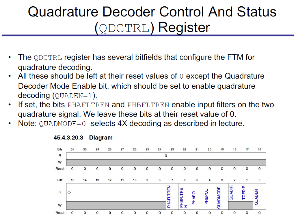
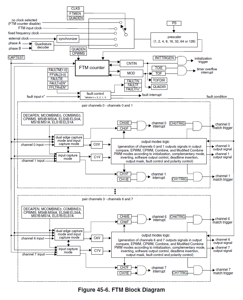
2. Quadrature Decoding with the FlexTimer
FTM have many registers, and each are 32 bits in width.
Every bitfield have its own function, whether its enable bits or setting values.
| QDCTRL Register | FTM block diagram |
|---|---|
 |  |
/* qd.c */
/******************************************************************************
* Function: init_QD
* Description: Initializes FlexTimer for Quadrature Decoding
******************************************************************************/
void initQD()
{
    /* Initialize Phase A and B input PCR */
    QD_PHA_PORT->PCR[QD_PHA_PIN] |= PORT_PCR_MUX(0b110); // Phase A
    QD_PHB_PORT->PCR[QD_PHB_PIN] |= PORT_PCR_MUX(0b110); // Phase B

    /* Set up FTM2 for Quadrature Decode */
    // Find the correct FTM -> find the register -> change to desired value
    FTM2->SC &= FTM_SC_FLTPS_MASK; // initialize scalar to 1
    FTM2->MODE |= FTM_MODE_WPDIS_MASK; /* Disable write protection (should already be disabled) */
    FTM2->MOD = 0xFFFF;
    FTM2->CNTIN = 0x0000;
    FTM2->QDCTRL = 0x1;   /* Enable QD mode */
    FTM2->CONF |= FTM_CONF_BDMMODE(0b11); /* Optional: enable in debug mode */
    return;
}

/******************************************************************************
 * Function:    updateCounter
 * Description: Returns an updated counter value that keeps track of absolute
 *              wheel position
 ******************************************************************************/
int32_t updateCounter()
{ /* setup */
    PREV_QDPC = CURR_QDPC;
    CURR_QDPC = FTM2->CNT & FTM_CNT_COUNT_MASK;
    TOTAL = TOTAL + (int16_t)(CURR_QDPC - PREV_QDPC); // correct
//    TOTAL = TOTAL + (CURR_QDPC - PREV_QDPC);  // faulty casting
    return (TOTAL);
} /* update wheel position */

/******************************************************************************
 * Function:    updateAngle
 * Description: Returns the angle of the wheel
 ******************************************************************************/
float updateAngle(){
    TOTAL = updateCounter();
    return TOTAL * 0.36 /4; // 4 is
};   /* convert counts to angle */
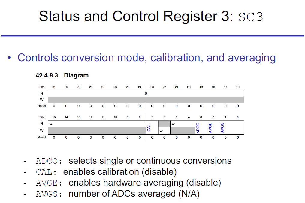
3. Analog-to-Digital Conversion (ADC)
| SC3 Register | ADC block diagram |
|---|---|
 | 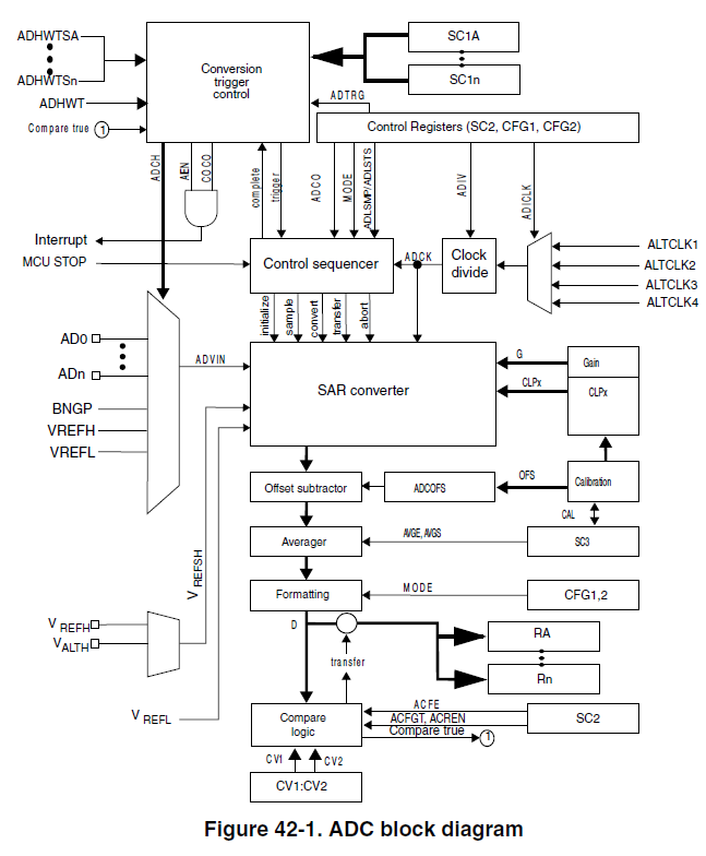 |
void init_ADC0_single(void)  {
    /* Table 27-9 Peripheral module clocking */
    /* 29.6.19 PCC ADC0 Register (PCC_ADC0) */
    PCC->PCCn[PCC_ADC0_INDEX] |= PCC_PCCn_CGC(0b0);    /* Disable clock to change PCS */
    PCC->PCCn[PCC_ADC0_INDEX] |= PCC_PCCn_PCS(0b001);  /* Select clock option 1 */
    PCC->PCCn[PCC_ADC0_INDEX] |= PCC_PCCn_CGC(0b1);    /* Enable clock */

    /*42.4.2 - ADC Status and Control Register 1 (SC1AA - SC1Z)*/
    ADC0->SC1[0] |= ADC_SC1_ADCH(0b11111);  /* Disable Module */
    ADC0->SC1[0] |= ADC_SC1_AIEN(0b0);      /* Disable interrupts */

    /*42.4.3 - ADC Configuration Register 1: CFG1 */
    ADC0->CFG1 |= ADC_CFG1_ADICLK(0b00);    /* Alternate clock 1 */
    ADC0->CFG1 |= ADC_CFG1_MODE(0b01);      /* 12-bit conversion (there are 8-bit, 10-bit) */
    ADC0->CFG1 |= ADC_CFG1_ADIV(0b00);      /* Prescaler=1 */

    /*42.4.4 - ADC Configuration Register 2: CFG2 */
    ADC0->CFG2 |= ADC_CFG2_SMPLTS(0b1100);  /* set sample time to 13 ADC clks */

    /*42.4.7 - Status and Control Register 2: SC2 */
    ADC0->SC2 |= ADC_SC2_ADTRG(0b0);        /* Software trigger, a conversion is initiated following a write to SC1A */
    ADC0->SC2 |= ADC_SC2_REFSEL(0b00);      /* use voltage reference pins VREFH & VREEFL */

    /*42.4.8 - Status and Control Register 3: SC3 */
    ADC0->SC3 |= ADC_SC3_CAL(0b0);         /* Do not start calibration sequence */
    ADC0->SC3 |= ADC_SC3_ADCO(0b0);        /* One conversion performed (single mode) */
    ADC0->SC3 |= ADC_SC3_AVGE(0b0);        /* HW average function disabled */
}


uint8_t ADC0_complete(void)  {
    /* 42.4.2.4 - COCO flag */
    return (((ADC0->SC1[0]) & ADC_SC1_COCO_MASK) >> ADC_SC1_COCO_SHIFT);  /*return COCO flag*/
}


uint32_t read_ADC0_single(uint16_t inputChannel)  {
    uint16_t adc_result=0;

    /* inform students of the mask and functions in header for ADCH */
    ADC0->SC1[0] &= ~(ADC_SC1_ADCH_MASK);          /* Clear prior ADCH bits */
    ADC0->SC1[0] |= ADC_SC1_ADCH(inputChannel);    /* Initiate Conversion */

    while(ADC0_complete() == 0); // wait for completion

    /* 42.4.31.2 - Data Result Register*/
    adc_result = ADC0->R[0];      /* For Software trigger mode, R[0] is used */

    /* Convert result to mv for 0-5V range */
    /* Hint: can this be done without floating point math for speed? */
    return  (uint32_t)(adc_result * 5000 / 4095);
}
4. Pulse Width Modulation (PWM)
| SC3 Register | ADC block diagram |
|---|---|
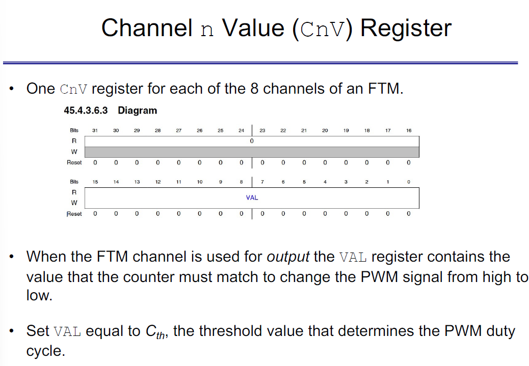 | 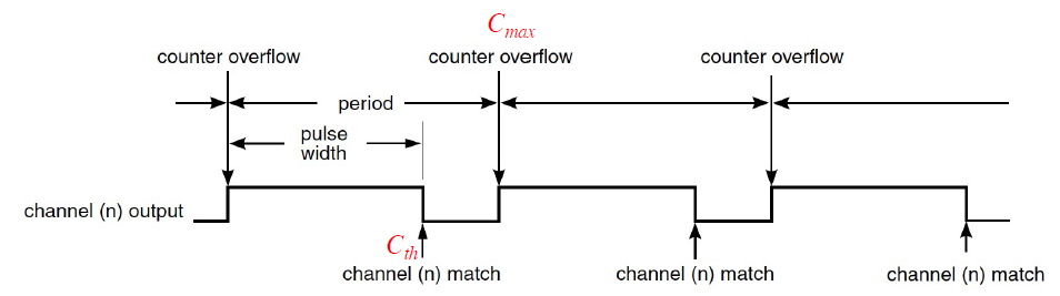 |
We will change the PWM duty cycle by changing the value of Cth by setting the VAL bitfield in the SCn register. However, C_thres could change during a counting cycle. S32K144 uses double buffering to assure PWM updates happen predictably.
Double buffered means we don’t directly update the VAL bitfield of the CnV register that specifies the duty cycle of the PWM signal. Instead we update the write buffer for the CnV register.
/* PWM.c */
static FTM_Type* FTM_MODULE[4] = FTM_BASE_PTRS;

/******************************************************************************
 * Function:    initPWMPCRs
 * Description: Initialize the pins for each respective output PWM
 ******************************************************************************/
void initPWMPCRs()
{
    /* Initialize motor output PCR */
    MOTOR_PORT->PCR[MOTOR_PCR] |= PORT_PCR_MUX(MOTOR_MUX);

    /* Initialize filter output PCR */
    FILTER_PORT->PCR[FILTER_PCR] |= PORT_PCR_MUX(FILTER_MUX);
}

/******************************************************************************
 * Function:    initPWM
 * Description: Initializes PWM - 45.5.7: Edge-Aligned PWM (EPWM) Mode
 ******************************************************************************/
void initPWM(int submodule, int channel, int frequency, float dutyCycle)
{
    /* 45.4.3.9 - Feature Mode Selection (MODE) */
    FTM_MODULE[submodule]->MODE |= FTM_MODE_WPDIS_MASK;  /* Write protect to registers disabled (default) */

    /* 45.4.3.2 - Status and Control (SC) */
    FTM_MODULE[submodule]->SC = 0x00000000; /* Clear the status and control register */
    FTM_MODULE[submodule]->SC |= FTM_SC_CLKS(0b11); /* Select external clock */

    FTM_MODULE[submodule]->COMBINE = 0x00000000; /* FTM mode settings used: DECAPENx, MCOMBINEx, COMBINEx=0  */

    /* Enable the respective channel */
    FTM_MODULE[submodule]->SC |= ((0b1 << FTM_SC_PWMEN0_SHIFT) << channel);

    /* Channel Control see S45.4.3.5 and Table 45-5 (S45.5.4) */
    FTM_MODULE[submodule]->CONTROLS[channel].CnSC = 0; /* Clear the register*/
    FTM_MODULE[submodule]->CONTROLS[channel].CnSC |= FTM_CnSC_MSB(0b1); /* MSB : Edge Align PWM */
    FTM_MODULE[submodule]->CONTROLS[channel].CnSC |= FTM_CnSC_MSA(0b1); /* MSA : Edge Align PWM */ // not sure about the number
    FTM_MODULE[submodule]->CONTROLS[channel].CnSC |= FTM_CnSC_ELSB(0b1); /* ELSB : High-true pulses */
    FTM_MODULE[submodule]->CONTROLS[channel].CnSC |= FTM_CnSC_ELSA(0b0); /* ELSA : High-true pulses */

    /* 45.5.7 - Edge-Aligned PWM (EPWM) */
    FTM_MODULE[submodule]->CNTIN = 0;    /* Always start counter from 0 */
    //  FTM_MODULE[submodule]-> MOD = cmax;  /* counter rolls over at MOD  */

    FTM_MODULE[submodule]->CONF |= FTM_CONF_BDMMODE(0b11); /* Optional: enable in debug mode */

    /* Set the PWM */
    setPWM(submodule, channel, frequency, dutyCycle);
}

/******************************************************************************
 * Function:    setPWM
 * Description: Sets the output PWM for a given channel in FTM_MODULE
 ******************************************************************************/
void setPWM(int submodule, int channel, int frequency, float dutyCycle)
{
    uint16_t cthres;
    uint16_t cmax;

    cmax = ((1.0/frequency)* PWM_CLOCK_FREQ)- 1;
    cthres = dutyCycle * (cmax + 1);

    FTM_MODULE[submodule]->MOD = cmax; /* Set the PWM frequency */
    // changing the value of Cth by setting the val bitfield in the SCn register
    FTM_MODULE[submodule]->CONTROLS[channel].CnV = cthres;  /* Set the PWM duty cycle */
}

/******************************************************************************
 * Function:    outputTorque
 * Description: Outputs the torque to the haptic wheel in N-mm
 ******************************************************************************/
void outputTorque(float torque)
{
    // Calculate duty cycle
    float dutyCycle = (torque/3162.5) + 0.5;

    // Apply DC_UPPER_LIMIT, DC_LOWER_LIMIT
    if(dutyCycle < DC_LOWER_LIMIT){
        dutyCycle = DC_LOWER_LIMIT;
    }
    if (dutyCycle > DC_UPPER_LIMIT){
        dutyCycle = DC_UPPER_LIMIT;
    }

    // Adjust the motor PWM
    setPWM(MOTOR_SUBMODULE, MOTOR_CHANNEL, MOTOR_FREQUENCY, dutyCycle);
}
5. Interrupts and Frequency Analysis
/* LPIT.c */
void enableLPIT(){
    /* 29.6.5 PCC LPIT Register  */
    PCC->PCCn[PCC_LPIT_INDEX] &= ~PCC_PCCn_CGC_MASK;  /* Disable PCC LPIT clock to change PCS */
    PCC->PCCn[PCC_LPIT_INDEX] = PCC_PCCn_PCS(0b110);   /* Clock source:  SPLL2_DIV2_CLK */
    PCC->PCCn[PCC_LPIT_INDEX] |= PCC_PCCn_CGC_MASK;   /* Enable clk to LPIT0 regs */

    /* 46.4.1.4.2 Module Control Register  */
    LPIT0->MCR = LPIT_MCR_M_CEN(0b1);     /* enable module clk (allows writing other LPIT0 regs)*/
}


void initLPIT(const uint8_t channel, const uint32_t frequency, const isr_t handler, const uint32_t priority) {
    /* 46.4.1.9.3 Timer Value Register   */
    LPIT0->TMR[channel].TVAL = ((1.0/frequency)* LPIT_CLK_FREQ)- 1;  /* channel timer start value */

    /* 46.4.1.6.2 Module Interrupt Enable Register */
    LPIT0->MIER = (0b1 << channel);    /* Timer Interrupt Enabled for Channel */

    /* 46.4.1.9.3 Timer Control Register */
    LPIT0->TMR[channel].TCTRL = 0; /* T_EN : Timer channel is disabled to set registers*/
    //  LPIT0->TMR[channel].TCTRL |= LPIT_TMR_TCTRL_MODE(0b00);  /* MODE :  32 periodic counter mode */
    //  LPIT0->TMR[channel].TCTRL |= LPIT_TMR_TCTRL_TSOT(0b0);  /* TSOT : Timer decrements immediately based on restart */
    //  LPIT0->TMR[channel].TCTRL |= LPIT_TMR_TCTRL_TSOI(0b0);  /* TSOI :  Timer does not stop after timeout */
    //  LPIT0->TMR[channel].TCTRL |= LPIT_TMR_TCTRL_TROT(0b0);  /* TROT : ignore external trigger */

    /* 46.4.1.7.3 Set Timer Enable Register   */
    LPIT0->SETTEN = (0b1 << channel);    /*SET_T_EN_n :  enable timer for channel */

    /* defined in interrupt_manager.c */
    INT_SYS_InstallHandler(LPIT_IRQn[channel], handler, (isr_t*) 0);
    INT_SYS_SetPriority(LPIT_IRQn[channel], priority);
    INT_SYS_EnableIRQ(LPIT_IRQn[channel]);
}


void clearFlagLPIT(const uint8_t channel){
    /* 46.4.1.5.3 Module Status Register  */
    LPIT0->MSR = (0b1 << channel);   /* clear TIFn */
}
/* lab5.c */
#define LPIT0_CHANNEL  0

double sineTable[10]; // Ten samples/period
int sineIndex = 0;
const float PI = 3.14159;

uint32_t input = 0;
int frequency, channel;
uint8_t dip1, dip2, dip3;

/* Interrupt A - Read Duty Cycle from Signal Generator */
void IsrA(void){
  uint32_t iAnalog;
    float dutyCycle;
    int freq;   //PWM frequency

    uint8_t dipswitch1;
    uint8_t dipswitch2;
    float m,b;

    /* Turn on LED */
    writeGPIO(3, 0, 1);

    /* Read sine value */
    iAnalog = read_ADC0_single(0); // read AN0 analog input

    /* Calculate PWM duty cycle */
    dipswitch2 = readGPIO(4,7);
    if(dipswitch2 == 1){
      m = 0.8;
      b = 0.1;
    }
    else{
      m = 0.2;
      b = 0.4;
    }
    dutyCycle = b + ((float)iAnalog / 5000) * m ; //y = m*(x/n) + b

    /* Set PWM frequency based on dipswitch */
    dipswitch1 = readGPIO(4, 6);
    freq = (dipswitch1 == 1) ? 60000 : 20000;
  //  frequency = 20000;
    /* Set PWM duty cycle and frequency */
    setPWM(MOTOR_SUBMODULE, MOTOR_CHANNEL, freq, dutyCycle);

    /* Turn off LED */
    writeGPIO(3, 0, 0);

    /* Clear interrupt flag */
    clearFlagLPIT(LPIT0_CHANNEL); //check: const type casting
}

/* Calculate Duty Cycle from sin() */
void IsrB(void){
    static int i = 0;
    float theta, duty_cycle;

    /* Turn on LED */
    writeGPIO(LED_BASE[0], LED[0], 1);

    /* Calculate and set PWM duty cycle */
    theta = 2*PI * ((float)i/10);
    i = (i+1) % 10;
    duty_cycle = 0.5 + 0.4*sin (theta);
    frequency = 60000;

    setPWM(MOTOR_SUBMODULE, MOTOR_CHANNEL, frequency, duty_cycle);

    /* Turn off LED */
    writeGPIO(LED_BASE[0], LED[0], 0);

    /* Clear interrupt flag */
    clearFlagLPIT(LPIT0_CHANNEL); // clear channel 0
}

/* Calculate Duty Cycle Table Look-up */
void IsrC(void){
    /* Turn on LED */
    writeGPIO(LED_BASE[0], LED[0], 1);

    /* Calculate and set PWM duty cycle */
    setPWM(MOTOR_SUBMODULE, MOTOR_CHANNEL, frequency, sineTable[sineIndex]);
    sineIndex = (sineIndex+1) % 10;

    /* Turn off LED */
    writeGPIO(LED_BASE[0], LED[0], 0);

    /* Clear interrupt flag */
    clearFlagLPIT(0); // clear channel 0
}

int main(){
    int index;
    float theta;
    initEECS461();
    enableLPIT();
    init_ADC0_single();

    /* Initialize PWMs  */
    initPWMPCRs();
    initPWM(MOTOR_SUBMODULE, MOTOR_CHANNEL, MOTOR_FREQUENCY, FILTER_DUTY_CYCLE);    // motor
    initPWM(FILTER_SUBMODULE, FILTER_CHANNEL, FILTER_FREQUENCY, FILTER_DUTY_CYCLE); // filter

    /* Initialize GPIO  */
    for(index = 0; index < 16; index++){
        initGPDI(DIP_BASE[index], DIP[index]);
        initGPDO(LED_BASE[index], LED[index]);
    }

    /* put the duty cycle in the sinTable */
    for(index = 0; index < 10; index++){
        theta = 2*PI *(index/10); ;
        sineTable[index] = 0.5 + 0.4*sin (theta);
    }

    /* Initialize LPIT  */
    initLPIT(LPIT0_CHANNEL, 1000, &IsrB, 0xC);

    while(1){
    }
    return 0;
};
6. Virtual Worlds with Dynamics
/* worlds.c */
//====================LAB 4================================
/***************************************************************************
 * Virtual Wall
 ***************************************************************************/
float virtualWall(float angle)
{
  float torque = 0;
  float k_wall = 500.0; // N-mm/degree
  if(angle < 0){
    torque = -k_wall * angle;
  }
  return torque;
}

/***************************************************************************
 * Virtual Spring
 ***************************************************************************/
float virtualSpring(float angle)
{
  float k_spring = 10; // N-mm/degree
  return -k_spring * angle;
}

//====================LAB 6================================
/***************************************************************************
 * Virtual Spring Damper
***************************************************************************/
float virtualSpringDamper(float angle, float velocity)
{
  float k_spring = 10;
  float b_damper = 0.4; // 0.64
  return (-k_spring * angle) + (-b_damper * velocity);
}

/***************************************************************************
 * Virtual Wall Damper
***************************************************************************/
float virtualWallDamper(float angle, float velocity)
{
  float torque = 0;
  float k_spring = 500;
  float b_damper = (k_spring * TIMESTEP) / 0.2;
  if(angle < 0){
    torque = (-k_spring * angle) + (-b_damper * velocity);
  }
  return torque;
}

/***************************************************************************
 * Virtual Spring Mass
***************************************************************************/
float virtualSpringMass(float angle)
{
    float torque, k, m, x1, x2;
    k = 17.7778;
    m = 0.45;
    static float x1_prev = 0;
    static float x2_prev = 0;

    // descrete time matrix form
    x1 = x1_prev + (TIMESTEP * x2_prev);
    x2 = ((-(k*TIMESTEP)/m) * x1_prev) + (x2_prev) + (((k*TIMESTEP)/m) * angle);
    // x2 = x2_prev + (((k*TIMESTEP)/m) * (angle - x1_prev));

    torque = k * (x1 - angle);
    x1_prev = x1;
    x2_prev = x2;

    return torque;
}

/***************************************************************************
 * Virtual Spring Mass Damper
***************************************************************************/
float virtualSpringMassDamper(float angle, float velocity)
{
    float torque, b, x1, x2;
    //  float K = 17.7778;
    //  float M = 0.45;
    float J = M;

    static float x1_prev = 0;
    static float x2_prev = 0;

    b = K * TIMESTEP;

    x1 = x1_prev + (TIMESTEP * x2_prev);
    x2 = (-((K*TIMESTEP)/M) * x1_prev) + ((1.0 - (b*TIMESTEP)/M) * x2_prev) + (((K*TIMESTEP)/M) * angle) + (((b*TIMESTEP)/M) * velocity);

    torque = K * (x1 - angle) + b * (x2 - velocity);
    x1_prev = x1;
    x2_prev = x2;

    return torque;
}

/***************************************************************************
 * Virtual Knob
***************************************************************************/
float virtualKnob(float angle, float velocity)
{
    //There are many ways this can be implemented
    float b, k, torque, angle_to_move;
    const int SCALE = 45;
    float angle_in_scale = 0;

    k = 30;
    b = 0.5;

    // find the right direction and angle to move
    angle_in_scale = angle - SCALE * (int)(angle/SCALE);
    // make the angle 0-20
    if(angle < 0){
        angle_in_scale += SCALE;
    }
    // find the right direction
    angle_to_move = SCALE/2 - angle_in_scale;
    torque = k * angle_to_move - b * velocity;
    return torque;
}
7. Control Area Network (CAN)
8. Autocode Genegration
Final Project
linkedin https://www.linkedin.com/in/yi-cheng-liu/
Github https://github.com/yi-cheng-liu
personal webpage https://yi-cheng-liu.github.io/